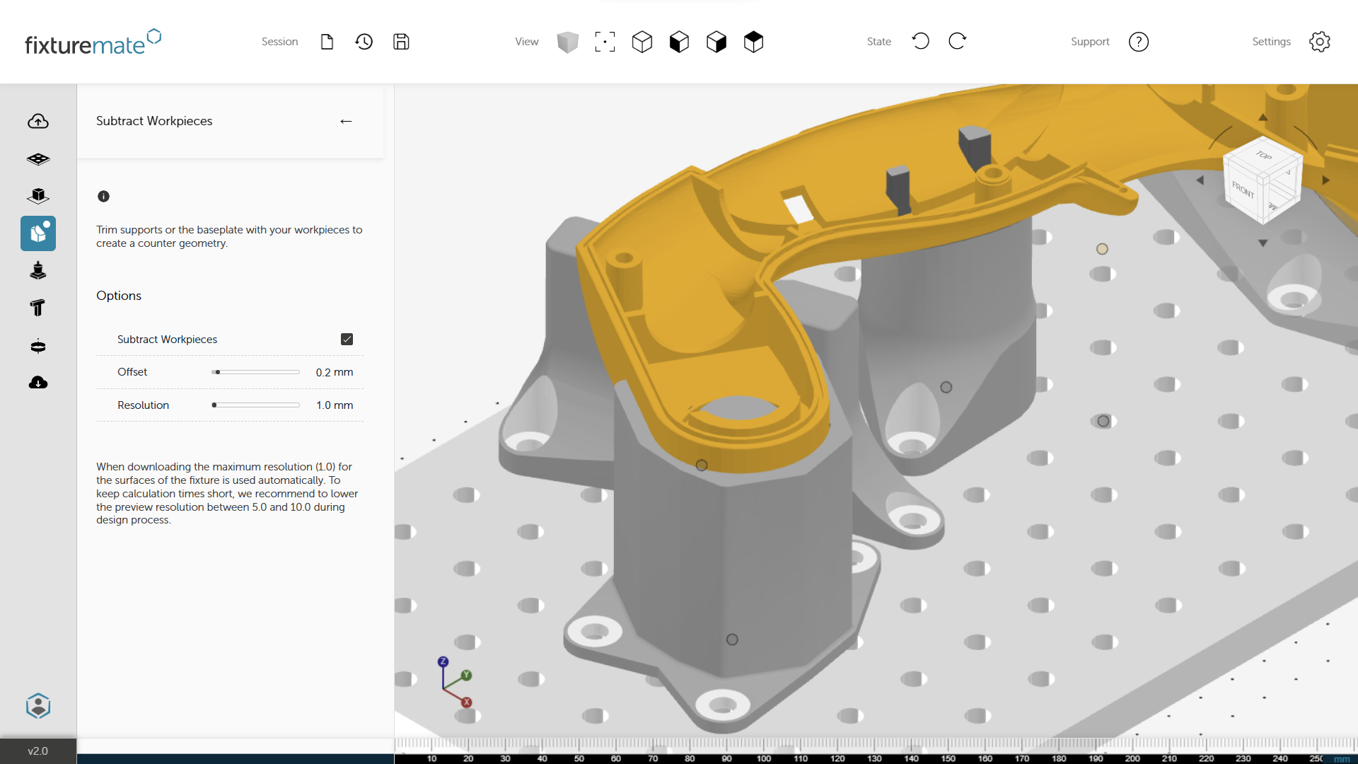
Easily create a negative
In just a few clicks, subtract complex geometries, avoid undercuts, and fine-tune offsets for a securely fitted fixture.
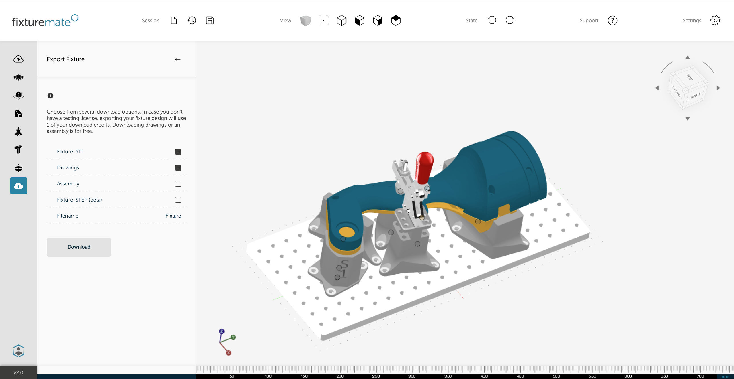
Seamless 3D printing integration
Exports are optimized for 3D printing, so once your design is complete, simply slice, 3D print, and deploy your custom fixture within hours.
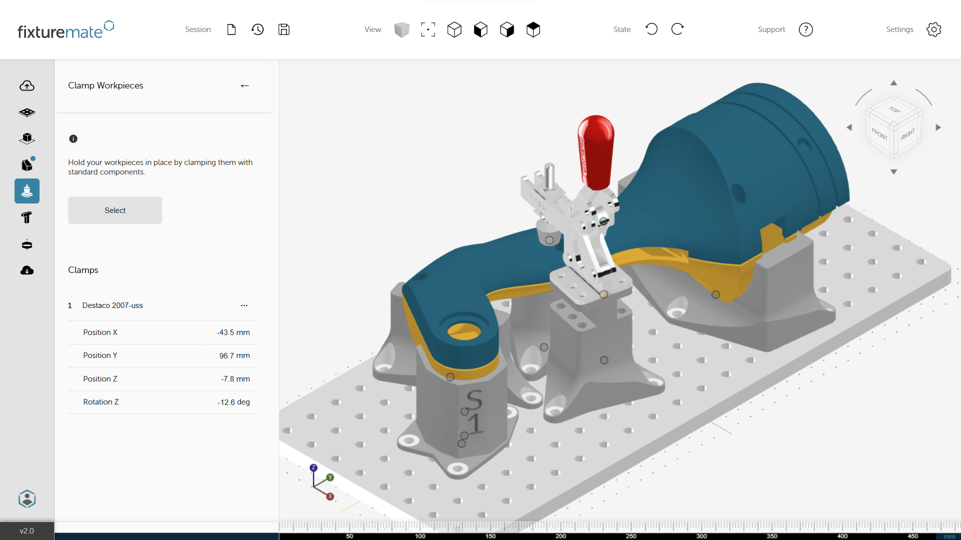
Industry-standard components included
A range of standard clamps and baseplates are available directly in fixturemate, saving you the hassle of creating these components from scratch.
How our customers rethink fixtures
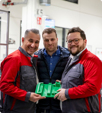
"In CAD we usually need two to four hours to produce a design, depending on the size of the part. With fixturemate we can produce a usable fixture in minutes."

"trinckle's fixturemate software has seamlessly integrated design automation into our additive manufacturing processes for tooling at Deutsche Bahn. The software has drastically reduced our design times and costs."
Assembly fixtures
Streamline assembly with exact part orientation for simple connections and mounting.
Learn more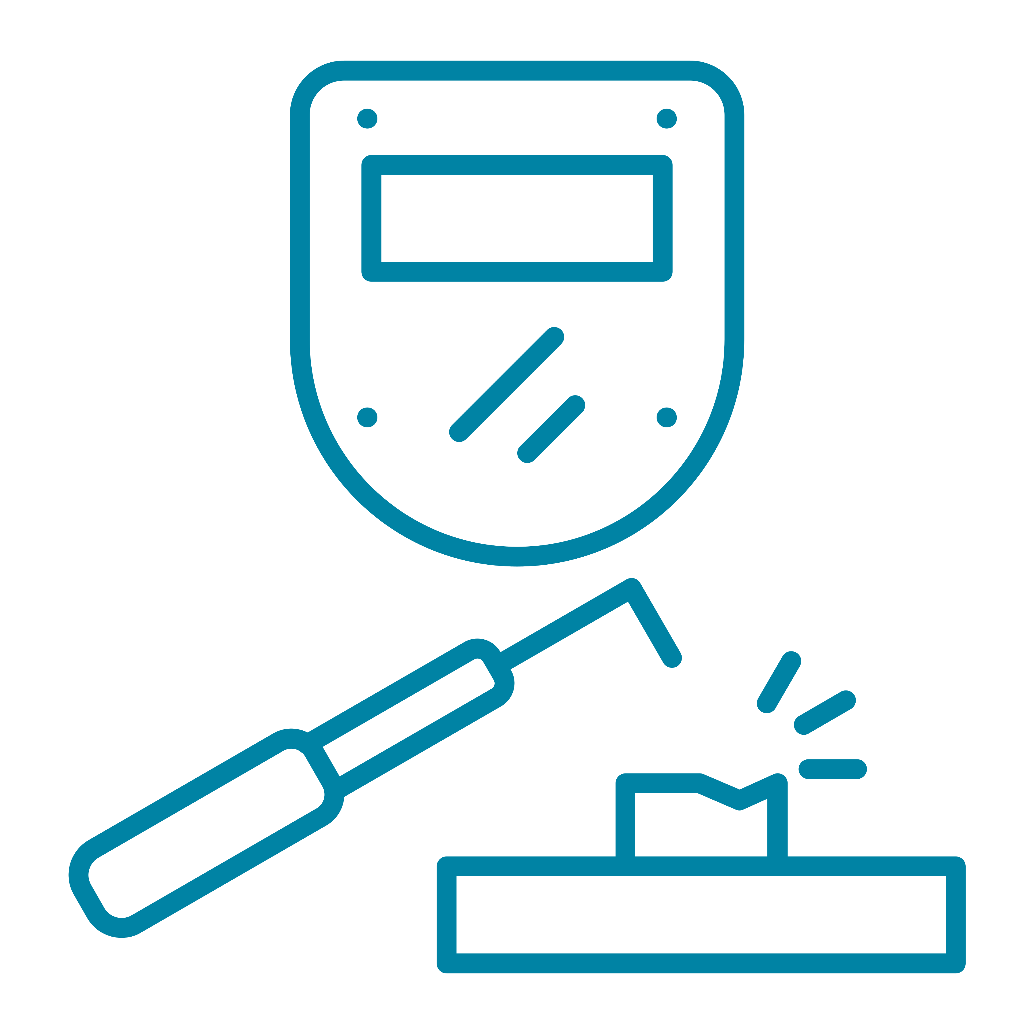
Welding fixtures
Ensure precise alignment and stability when bonding or welding parts, guaranteeing consistency.
Learn moreInspection gauges
Use Go/No-go gauges to swiftly check the accuracy of parts after production or assembly.
Learn more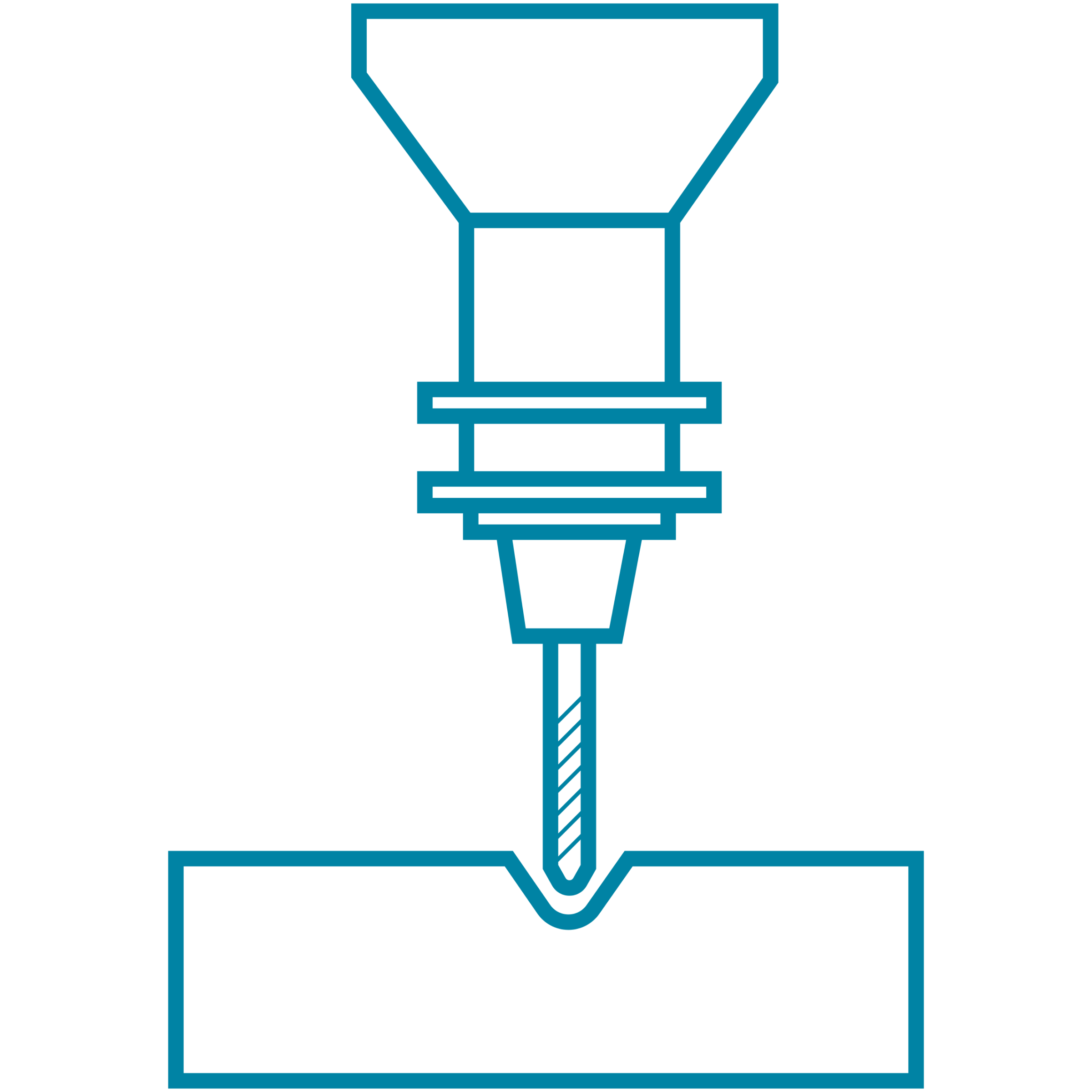
Machining fixtures
Create strong and stable custom workholdings for turning, drilling, and milling operations.
Learn more